
Information on operating system versions, and on module files. Below there is also a subsection on the internal working of the operating systems. That section is still incomplete, and may contain errors.
The TWIN machine was sold under three brand names, using at least that many operating systems. From the launch around September 1977 to around 1982 there were several updates to each of these operating systems. Although it seems likely that most of these operating shared architecture, operating instructions and source code, I do not fully know where similarities end, nor what the differences are between versions of the same operating system.
Copies of SDOS (for the Signetics TWIN), UDOS (for the Millennium Universal One) and TEKDOS (for the Tektronix 8002) can be found on available disk images. So far I have looked at the disk images from the Stuttgart computer museum, the Tektronix and Millennium directories on bitsavers.org, and the disks that came with my ECA system. The collection can be downloaded below. My HM system came with a interesting collection of disks, which is available for download.
To load DOS from a disk, a small boot EEPROM contains code that reads contents from tracks 1 to 4 into master memory starting from address 0000. The EEPROM is only 256 bytes long, and half of that is taken up by jump instructions for interrupt handler routines. Note that the contents of the EEPROM are in reversed order, probably because the address lines on the system bus are inverted. The file at bitsavers contains the EEPROM-contents in their stored order; file boot.bin below contains the contents as seen by the master cpu.
Based on information gleaned from documentation, dates of copyright notices and the identity-strings in modules on disk images I have compiled the following timelime. This is still very much work in progress!
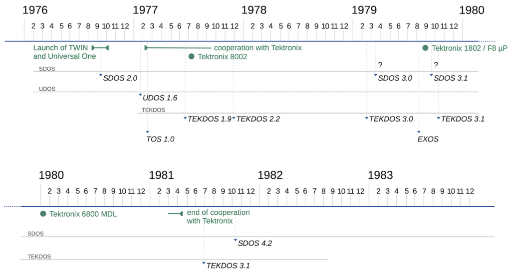
One outlier is TOS version 1.0, which was found on an original Signetics disk with the ECA system. A clue to its origin can be found in the module for the Editor: the editor contains a command to return to the operating system. This command is either SDOS, UDOS, or SUSPEND (for SDOS, UDOS and TEKDOS respectively). For TOS this editor command is “SDOS”. The fact that TOS was found on an original Signetics-labeled disk most likely means that we are dealing with an internal test-version of SDOS.
Some of the disks that came with the HM system contain another variant: EXOS. EXOS shares some of the unique features of TOS (such as a real-time clock and certain builtin commands), still has the SEARCH command, and must therefor be an evolved version of TOS. EXOS announces itself with the version string “** EXOS Nat.Lab. **“. NatLab is the famed research and development lab of Philips, Signetics’ parent company. NatLab was involved with TWIN development, and developed a Pascal compiler for the TWIN. In fact, PASCAL is one of the built-in commands of EXOS. EXOS also includes a typesetting program, supports debugging of the Z80 microprocessor, and has an assembler for the 8748 microcontroller.
Not all release dates are known exactly. At first glance it looks like the major and minor versions numbers are synchronised between SDOS, UDOS and TEKDOS.
SDOS 1.0 No known documentation for this version. Its properties are only known in comparison to SDOS 2.0, based on the TWIN Technical Note SW002. The LDIR command does not show disk statistics.
SDOS 2.0 Described in TWIN Technical Note SW002. Command LDIR also prints disk statistics, the VERIFY command requires a drive number. All RAM is initialised on startup, to support the parity checks on the new dynamic RAM card.
SDOS 3.0 The SEARCH command has been removed. The SLAVE command is replaced by the ICE command (which takes different parameters). Adds CMPF and DFIL commands for file management. Adds MOVE, FILL, READ, WRITE, UPR commands to maniplate slave memory.
SDOS 3.1 The minimum version required for the new Real-time Hardware Analyzer card.
SDOS 4.0 Adds commands to compare two files, dump a file in hex format
I will updated this page when new information is discovered.
Security model
This section can be brief, because the TWIN security model is mostly absent. Access to the machine is controlled physically by a key. There is no concept of signing on, password protection or any other access control. They only built-in limitation is that certain Supervisor functions are restricted to DOS modules (those running as job 1 or 2, or those running on the slave processor as job 3 provided that their filename starts with the special character Ctrl-O).
Module files
Modules contain executable code that can be loaded into master or slave memory. Almost all DOS commands are provided as modules. DOS’ module files are stored in hidden files: the first character of the filename is Ctrl-O (h'0F'). Note that LDIR can show hidden files on a disk when using “LDIR .” .
Modules consists of a 128-byte (one sector) header, followed by data bytes. Most often the data bytes are consecutively stored at the starting address, but the actual load sequence is dictated by load commands listed in the header. See the table below; offsets are hexadecimal, lengths are decimal.
Load module layout
00..02   3   "MOD"
03       1   01=overlay area 1, 02=overlay area 2, 03=slave memory
04..05   2   Load address (slave's perspective)
06..07   2   End address
08..09   2   Start address (first address of execution)
0a..1f  22   Identity (e.g. module name, version, date), 0d terminated text.
20..7f  var  Load commands (variable length)
From offset 20 onwards there are one or more load commands. Load commands start with a command byte, followed by one or two bytes, depending on the command. In the explanation below the command byte is separated into its eight bits (0 or 1, a letter indicating a special function, or ‘x’ for don’t care).
Set Base: bbxx-x00x
bb is the bank. The two bytes following this command byte indicate the base address from the master’s perspective. This base address is used for the subsequent Read Data command.
Read Data: abcd-e01z00za bcde is the number of sectors to read, minus 1. The byte following this command byte is the length for each of these read operations. Typically this length is h'80' (128) for one full sector, but when the number of sectors is one (the last sector to be read), the length will often be less than 128.
Load End: xxxx-x10x
Indicates the end of the list of load commands. Some of the bits may have a function, but this I have not figured out yet.
DOS reserves two memory areas for modules: overlay area 1 (address 1500-187f) and overlay area 2 (address 1880-1bff). These areas are small, just under 900 bytes each. Some DOS commands actually consist of two modules. The LDIR command for example, in module file “Ctrl-O L”, is loaded into overlay area 1. LDIR then verifies that overlay area 2 is not in use, and loads module file “Ctrl-O O” into overlay area 2.
The design of modules seems overly complex. Note also that code that is too large for overlay areas 1 and 2 combined has to be loaded into slave memory, and then has to be executed by the slave processor.
I wrote a Perl-script to parse the header contents of modules.
For example, the module for the MACRO command:
Module file   :  [@8]
Is module?    :  probably
Identity      :  [** MACRO VER 2.1 **]
Overlay       :  slave memory
Address range :  0040 - 1a13
Start address :  0e05
Load commands :
  - bank/base  0/4040
  - 1 partial blocks of 64 bytes into 4040 ~ 407f
  - bank/base  0/4080
  - 32 full blocks into 4080 ~ 507f
  - bank/base  0/5080
  - 19 full blocks into 5080 ~ 59ff
  - bank/base  0/5a00
  - 1 partial blocks of 20 bytes into 5a00 ~ 5a13
  - end.
For comparison, the header of the MACRO module looks like this (with the nine load commands highlighted).
00000000: 4d4f 4403 0040 1a13 0e05 2a2a 204d 4143  MOD..@....** MAC
00000010: 524f 2056 4552 2032 2e31 202a 2a0d 3031  RO VER 2.1 **.
00000020: 0040 4002 4000 4080 fa80 0050 8092 8000  .@@.@.@....P....
00000030: 5a00 0214 040d 2020 2020 2020 204c 0044  Z....
00000040: 492c 3320 203e 4d53 000d 2020 2020 2020
00000050: 2042 0041 2020 2020 2044 4953 004c 2020
00000060: 2020 2020 2020 0020 2020 2020 4449 5350
00000070: 0041 5920 4d45 5353 4147 000d 2020 2020
Note that unused bytes of the header (padding of the Identity string, and bytes from the Load End command onwards) contain random data.
DOS Internals
This section is going to be long, and is currently only partially complete and possibly incorrect in places. I expect to publish updates regularly.
The operating systems for the TWIN (SDOS, UDOS, TEKDOS, and TOS) share a common ancestry. I use the term ‘DOS’ as the generic word for all. To understand their working I started reverse-engineering on the earliest, and therefore hopefully most simple version: TOS v1. TOS already turned out to be quite complex internally.
Application programs and modules make use of DOS’ service functions. This is done through a Supervisor Call (SVC). The calling program supplies a Service Request Block (SRB), 8 to 12 bytes containing all relevant information for the request. More details on the SVC interface can be found in one of the Operator Manuals.
Jobs
DOS is multitasking. It can handle four jobs, although only one of those can be running at any time (no multiprocessing). Jobs can be suspended from the console and restarted. While one job is waiting for slow I/O operations to finish another job can continue processing.
Job 0 is for DOS internally, when handling service calls or running a procedure (“batch file”).
Job 1 is for modules running in overlay area 1.
Job 2 is for modules running in overlay area 2.
Job 3 is for programs running on the slave CPU.
DOS maintains a job control block, which is a set of tables of length four, indexed by the job number. Most table entries are byte-values, those that contain addresses are word-values (two bytes).
2050 JobStatus (byte):  Job current state
	0  job idle (no job)
	1  job loaded
	2  job ready to start
	3  job executing
	4  job in i/o wait
	5  job i/o complete
	6  job suspended
	7  job being aborted
	8  job self paused
2054 JobPrevStatus (byte):  Job previous state, values same meaning as current status
2058 JobChanAssigned (byte):  Job assigned channels (bit mask, 0/1 = (un/)assigned)
205c JobChanActive (byte):  Job channels with an in-progress SVC (bit mask, 0/1 = (not/)active)
2060 JobWaitingForCh (byte):  Job waiting for channel (bit mask)
2064 JobChanIOComplete (byte):  Job channel has completed I/O task (bit mask)
2068 JobWait (byte): (JJO), number of job that this job is waiting for (zero if none)
			Uses ExtraReturntab when waiting is done.
206c JobIdx (byte):  JID??
2070 JobBank (byte):  Job bank
2074 ModuleStartOffset (byte):  See information on modules.
2078 ModuleStartAddr (word):  See information on modules.
2080 SRBreturntab (word):  SRB return addresses
2088 ExtraReturntab (word):  ?? addresses
2890 JobStatusCh0 ~ JobStatusCh7 (byte): per channel the status of that channel
20b0 JobDeviceCh0 ~ JobDeviceCh7 (byte): per channel the device used by that channel
20d0 (end of job control block)
DOS API
DOS exposes very few function to application programs. The interface consists of a few routines and subroutines at address 2000 and further.
2000 API_SupervisorCall: the main entry into DOS service functions. The calling program supplies the address of the Service Request Block (SRB) in registers R2R3. The SRB contains the return address. Called as a routine, using a branch instruction.
2003 API_IntSaveState: saves all registers, for later restore. Called as a subroutine.
2006 API_IntRestrState: restore previously saved registers. Called as a subroutine.
2009 API_ConvertASCtoNum: converts a string representing a hexadecimal number into a binary number. Called as a subroutine.
200C API_FileReadyIOComplete: indicates that file operations are complete and the file can be closed.
200F API_Dispatcher: the job scheduler. Not normally called; programs and modules suspend or abort using Supervisor calls, which will run the dispatcher automatically.
2012 API_QueueError: report a module ID and error number. DOS will display the error number on the console when no other job is scheduled by the dispatcher.
2015 API_LookupDeviceName: parse a device name (such as CONI or LPT1).
2018 API_ParseCommand: parse and run a DOS command.
201B API_SkipToCmdBuff1Param: used to parse the commandline parameters.
Channels
Jobs perform input/output operations not directly on devices but on channels. Each job can use at most 8 channels. Before a channel can be used it must be assigned using a Supervisor call to a device name (such as CONO for console output, or LPT1 for the system printer), or to a filename. All further I/O operations (reading, writing, deleting the file, renaming the file) are performed with reference to the channel number. When a channel is no longer needed it must be closed using a Supervisor call.
Data on channels is kept in the job control block, using JobStatusCh0 to JobStatusCh7 and JobDeviceCh0 to JobDeviceCh7. Job status is a bit mask. Bit 80 indicates that the channel is assigned. Bit 20 indicates that it is writeable. Other bits to be determined. The device indicates an offset into the device table.
When assigning a channel to a file that does not exist, that file will be created. There is often a sequence of assigning a file, testing whether a new file was created, and deleting that new file if so.
Devices
DOS can handle at most 16 physical devices. CONO, CONI, and the floppy disk are examples of sharable devices which can be assigned to more than one channel. The LPT1, HSPT, and TTYR are non-sharable devices and can only be assigned to one channel at any given time. Which devices are installed by default varies between DOSes. Device drivers can be “loaded” by patching DOS.
DOS maintains a Device Control Block: a list of tables, each 16 entries long. Indices into the tables are shown below. Note that the assignment of devices to indices may differ slightly from DOS to DOS. The ERRQ device is a pseudo-device. Writing to it will report errors, similarly to a call to API_QueueError. The MEM device is a pseudo-device for reading and writing to memory locations. It is not used in TOS, but was introduced in a later version.
dvCONI		EQU	0
dvCONO		EQU	1
dvLPT1		EQU	2
dvHSPT		EQU	3
devERRQ		EQU	4	; shared by error queue and prom programmer
devPRM		EQU	4
dvTTYR		EQU	5
dvOPTION	EQU	6
dvUSR1		EQU	7
dvUSR2		EQU	8
dvUSR3		EQU	9
dvUSR4		EQU	10
dvUSR5		EQU	11
dvUSR6		EQU	12
dvUSR7		EQU	13
devMEM		EQU	14
dvFDSK		EQU	15
Most tables in the device control block contain byte-values, those that contain addresses are word-values (two bytes). The jump table JmpDevhandlerBXA and the table with device names are three and four bytes respectively.
210f DevGetIdx (byte): read pointer into the ring buffer
211f DevPutIdx (byte): write pointer into the ring buffer
2346 DevBusy (byte): busy-state of the device
	0  device ready
	1  device busy
	2  device down
2356 DevStatus (byte): device state
	0  drive state unknown
	1  drive dsb set
	2  drive down
2366 DevBufIndex (byte): I/O buffer index
2376 DevBufCount (byte): I/O buffer count
2386 DevBufEchoCnt (byte): I/O buffer echo count
2396 DevFCB (byte): active index into the file control block
23a6 DevFnCode (byte): Supervisor function being handled (active)
23b6 DevBank (byte): bank switch
23c6 _DevIOAddr (word): I/O buffer address
23e6 DevRingbufAdr (word): starting address of the device's ring buffer
2406 DevID (byte): device ID. Is index+1, but -1 (0xff) indicates disk file.
2416 DevAvail (byte): device Availability. Bit mask:
       01  shareable
       80  down
2426 DevType: device type. Bit mask:
       01  can read
       02  can write
       10  sys abort
       40  binary (otherwise ascii)
2436 JmpDevhandlerBXA: Jumps to Device Handlers, 3 bytes each, unconditional branch instructions for use with the 2650 BXA instruction.
2466 Device Names, strings of 4 bytes each, not 0D terminated. Special devices start with 0x0f (just like special filenames do)
24a6 (end of the device control block)
Each device can have a small ring buffer. Ring buffers are used to stash a short amount of data. They can be at most 63 bytes long, but are often much shorter. The ring buffer for data received from the console, for example, is only two bytes deep. Ring buffers have a pointer for reading and a pointer for storing data. Both wrap around, to create a ring-like structure. When the pointers point to the same position the buffer is either completely full or completely empyty. The first byte of the ring buffer contains the buffer length in the lower six bits. Bits 80 and 40 are indicators: 80 indicates a buffer full condition, 40 indicates that the buffer is empty.
Files
DOS can handle 8 disk files plus 14 files that are associated with devices such as CONO or LPT1. The internal file control block consists of tables that are 22 items long, but tables that refer to disk I/O are only 8 items long. Many of the latter have more than one function. For example FileLastSectLen normally contains the length of the last sector (as stored in the directory), but contains the potential directory sequence number when the file is being created.
2150 FileState (byte, length 22): state of the file
	0  free
	1  assigned
	2  open
	3  busy
	4  ready
	5  end of file/data
	6  abort
2166 FileUsedByJob Job
217c FileBank Bank
2192 FileChan Channel number
21a8 FileFnCode SVC function code
21be FileDevStatus Physical device status
21d4 FileIOStatus I/O complete status: assume same values as SVCs
21ea FileIOCount I/O buffer byte count
2200 FileDskbuf I/O buffer addr
222c FileSRB SRB addr
2258 FileSVCRetAdr SVC ret addr
2284 FileRetAdr chan I/O complete ret addr
22b0 FileDskCmd command (same as Command for direct disk IO?)
22c6 FileDrive
22ce FileSector
22d6 FileTrack
22de FileSRBbuf
22ee FileDirSeqNum index of file within the directory
22f6 FileCntToDo remaining number of bytes for I/O operations
22fe FileNumSectors length of the file, in sectors
230e FileNumSectRemain number of unread (unwritten) sectors in the file
231e FileLastSectLen length of the last sector, in bytes
2326 FileUnknown2 (scratch area)
232e FileUnknown3 (scratch area)
Supervisor call functions
The Supervisor can handle 32 functions, but using modifiers the total number of functions is larger.
Function codes
  7 6 5 4 3 2 1 0
  | | | | | | | +-- c0
  | | | | | | +---- c1
  | | | | | +------ c2
  | | | | +-------- c3
  | | | |
  | | | +---------- c4
  | | +------------ 0/1 = Char/Block ; special assign
  | +-------------- 0/1 = Ascii Line/Binary
  +---------------- 0/1 = Proceed/Wait

srbFnRead	EQU	H'01'
srbFnWrite	EQU	H'02'
srbFnClose	EQU	H'03'
srbFnRewind	EQU	H'04'
srbFnDelete	EQU	H'05'
srbFnRename	EQU	H'06'
srbFnDirectIO	EQU	H'07'   for the Floppy Disk device
srbFnAssign	EQU	H'10'
srbFnTime	EQU	H'11'
srbFnOvlAddr	EQU	H'12'
srbFnParam	EQU	H'13'
srbFnDevType	EQU	H'14'
srbFnDevStatus	EQU	H'15'
srbFnLastChar	EQU	H'16'
srbFnLoadOvl	EQU	H'17'
srbFnExecOvl	EQU	H'18'
srbFnSuspend	EQU	H'19'
srbFnExit	EQU	H'1A'   to exit without closing open channels
srbFnPause	EQU	H'1B'
srbFnSlvParam	EQU	H'1C'
srbFnClkTime	EQU	H'1D'	only TOSv1
srbFnSlvMem	EQU	H'1D'	not in TOSv1
srbFnClkDate	EQU	H'1E'	only TOSv1
srbFnAbort	EQU	H'1F'   to exit cleanly

Modifiers
srbFnBlock	EQU	H'60'   special+block indicate raw disk sector I/O
srbFnSpecial	EQU	H'20'   a marker for "special" variants of functions
srbFnBinary	EQU	H'40'
srbFnWait	EQU	H'80'
A normal read or write operation will handle a string terminated by Carriage Return. The actual number of characters read or written depends on the length of the string, which may be less than the requested number or size of the buffer. A binary read or write will act on the exact number of bytes requested.
Each call to the Supervisor requires a Service Request Block. The size of the block may differ.
Ofs   Dir Meaning
00     <  Function code (as above)
01     <  Channel number
02     >  Status code
03     >< Data
04     >< Count
05     <  Length
06 07  <  Buffer address
08 09  <  Return address
0a 0b  <  Address of direct I/O command bytes
When an SVC is invoked by the slave, only the first 8 bytes are used. When an SVC is invoked by a module or within DOS itself, the return address needs to be specified in the next two bytes. When the requested operation is finished execution will resume at this address. Only for direct I/O operations on the floppy disk controller (function code 7) the address of the four controller instructions needs to be specified.
The direction indicates whether the data is supplied by the caller for use by the Supervisor, or whether the Supervisor will supply the data when returning control to the caller. Some fields are bi-directional. See the Operator Manuals for details on SVC calls.
In practice you will see that modules use a single byte SRB for Exit, Pause or Abort functions. Sometimes a trick is employed whereby the address of the jump-to-Supervisor instruction is used as the SRB address. An unconditional branch instruction has 2650 opcode 1F, matching the code for the Abort function:
      lodi,r2  <Exit
      lodi,r3  >Exit
Exit  bcta,un  API_Supervisor
Because the continuation address is specified in the SRB, code using a sequence of Supervisor calls can be difficult to read and understand.
I/O ports
DOS reserves a number of extended I/O ports for controlling the TWIN system itself. Most of the port addresses are hard-coded into the hardware modules. The GPIO General Purpose I/O module is the exception: it can be assigned to any free I/O port.
* Extended IO Ports
ioPort_HWAStatus	EQU	H'C0'
ioPort_SelectSlave1	EQU	H'E0'
ioPort_SelectSlave2	EQU	H'E1'
ioPort_SelectSlave3	EQU	H'E2'
ioPort_SelectSlave4	EQU	H'E3'
ioPort_ConsoleData	EQU	H'E8'
ioPort_ConsoleControl	EQU	H'E9'
ioPort_DiskLPTControl	EQU	H'EA'
ioPort_DiskLPTData	EQU	H'EB'
ioPort_IntervTimerControl EQU	H'EC'
ioPort_MasterMemProtect	EQU	H'ED'
ioPort_CommonMemBank	EQU	H'EE'
ioPort_SVC6		EQU	H'F2'
ioPort_SVC5		EQU	H'F3'
ioPort_SVC4		EQU	H'F4'
ioPort_SVC3		EQU	H'F5'
ioPort_SVC2		EQU	H'F6'
ioPort_SVC1		EQU	H'F7'
ioPort_DebugControl	EQU	H'F8'
ioPort_DebugCommand	EQU	H'F9'
ioPort_JumpAddrLo	EQU	H'FA'
ioPort_JumpAddrHi	EQU	H'FB'
ioPort_BPAddr1Lo	EQU	H'FC'
ioPort_PCLastLo		EQU	H'FC'
ioPort_BPAddr1Hi	EQU	H'FD'
ioPort_PCLastHi		EQU	H'FD'
ioPort_BPAddr2Lo	EQU	H'FE'
ioPort_PCNextLo		EQU	H'FE'
ioPort_BPAddr2Hi	EQU	H'FF'
ioPort_PCNextHi		EQU	H'FF'
Some ports can only be read while others can only be written to. For some ports the meaning is different for reading and writing. Ports FC/FD for example will write the address for Breapoint 1, but retrieve the Last Program Counter address when read. For several ports DOS keeps an internal copy of their current value, because that value can only be written and not read. For example, 2024 DebugCommand will always mirror the value of ioPort_DebugCommand.
The meaning of bits for each port is explained below. The strings in italics explain the meaning of the bits; character x indicates that that bit is not used.
C0 Harware analyzer control
PRPM-FATM
01 access mode
02 trace mode
04 arm stop on address compare plus count
08 fetch don't care
10 M/IO don't care
20 M/IO polarity
40 R/W don't care
80 R/W polarity

E0-E3 Slave command byte
AUUI-SSBB
03 memory protect base
	00 = base 0
	01 = base 16K
	10 = base 32K
	11 = base 48K
0c memory protect block size
	00 = no protect, 16K
	01 = not used [Slave block diagram says: 16 K protect, bit 14 override]
	10 = 32K (base 0 or base 32K only), bit 15 override
	11 = 16K
10 interrupt enable
60 user mode, ICE mode
	00 = mode 0, normal
	01 = mode 1, user I/O, system (slave) memory
	10 = special instr. only
	11 = mode 2, full user mode, user IO and memory
80 active/inactive

E9 Console Status (READ)
xxxP-FOED
01 data available
02 transmit buffer empty
04 data overrun
08 framing error
10 parity error

E9 Console Control (WRITE)
xxxx-xEPR
01 paper tape reader on (one byte at a time)
02 parity select
04 enable TTY interrupts

EA Floppy/LPT status (READ)
Lxxx-xxFP
01 printer busy =0
02 printer fault (power off, out of paper, disconnected) =0
80 flag =1 (controller has data or can accept data)

EA Floppy/LPT control (WRITE)
xxPD-xCCS
01 Strobe =0
06 C1 C0
10 enable disk interrupt
20 enable LPT interrupt

EB Disk status byte (READ after Start I/O, Reset or Printer strobe)
xxIE-WDUx
02 Unit check =1
04 Device not ready =1
08 Write protect =1
10 Error recovery =1
20 Illegal operation =1

F8 DebugControl (inverted: active=0)
xxAT-WRWR
01 bkpt 1 at read =0
02 bkpt 1 at write =0
04 bkpt 2 at read =0
08 bkpt 2 at write =0
10 tracing active, single cycle =0
20 debugging active / sequencer enable =0
C0 unused

Debug Command F9 (inverted: active=0)
xxxx-MJIR
01 forced reset =0 [FE]
02 forced interrupt (not used on 2650 slave) =0 [FD]
04 forced jump =0 [FB]
08 interrupt mask (tracing and breakpoints interrupts) =0 [F7]

xx+5 GPIO RS232 Status 2 (READ)
SRCI-xxxx
10 Ring indicator =1
20 Carrier detect =1
40 Data Set Ready DSR =1
80 Clear to Send CTS =1

xx+6 GPIO TTY/RS232 Status (READ)
xxxP-FOED
01 data available
02 transmit buffer empty
04 data overrun
08 framing error
10 parity error

xx+6 GPIO TTY/RS232 Control (WRITE)
xxxx-xEPR
01 paper tape reader on (one byte at a time)
02 parity select (1=even, 0=odd)
04 enable TTY interrupts
08 local mode, RS232 only =1
10 originate mode, RS232 only 1=answer, 0=orig
20 send restraint, RS232 only =1
40 data terminal ready DTR, RS232 only =1
80 request to send RTS, RS232 only =1