
Central Data Corporation sold a single-board 2650-based microcomputer. It was published in the April edition of the American Radio Electronics magazine in 1977.
I have redrawn the schematics using Abacom’s sPlan software. I corrected a few tiny errors, and perhaps introduced one or two new ones. Searchable PDF and the sPlan source files are below. Signals marked with a bullet are active-low; normally active-low is indicated by an overline, but that is cumbersome in sPlan.
Recent changes:
- 29 dec 2023: Corrected actual connections to IC65, in all three schematics. This was incorrect in the original Radio Electronics schematics.
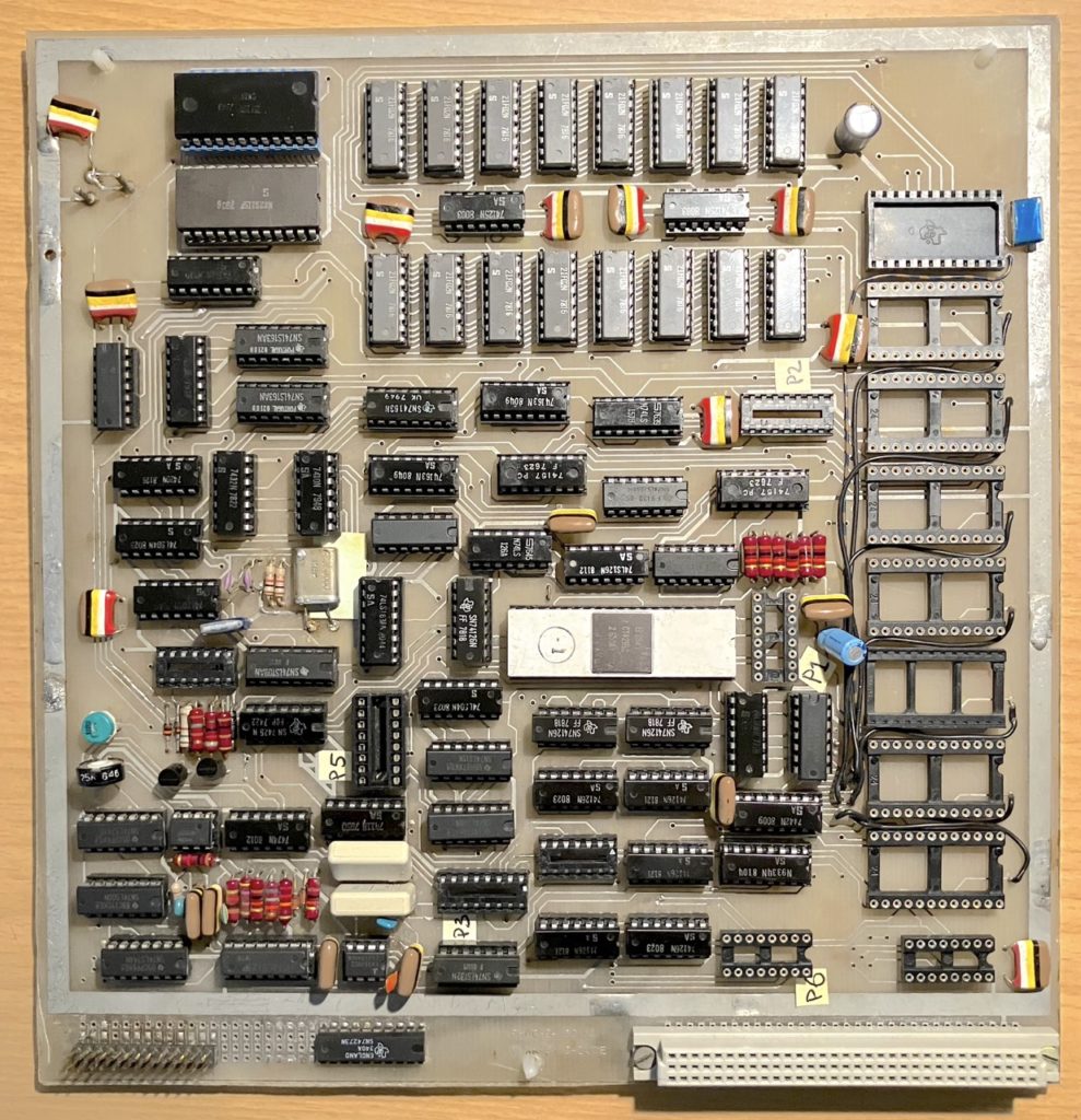
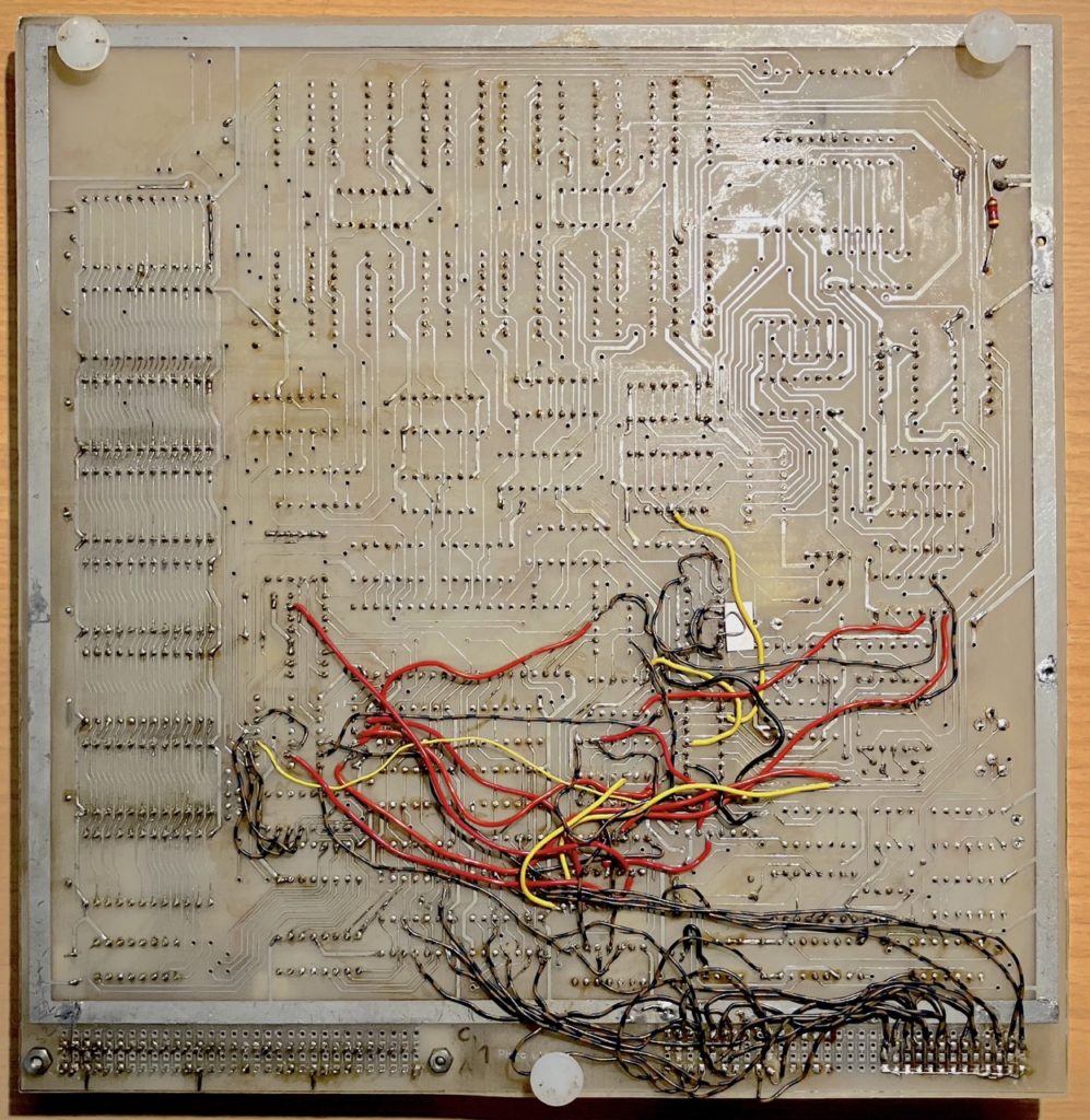
I do not own this board, but somewhere on the Vintage Computer Federation‘s forums I found photos of the front and back. Click the images for larger versions.
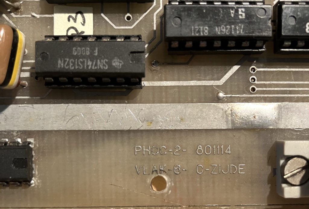 Based on the Central Data board, a group of enthousiasts in the Netherlands (or Germany? the history is unclear) created a clone. I obtained one of their boards, back in the early 1980’s. It is marked PHCC-2 801114, presumable “Philips Hobby Computer Club” – version 2 – 14 November 1980. The only difference to the Central Data board that I found is that it uses 82S115 PROM chips instead of 3624 chips. The decoding of control signals is slightly modified to accommodate the 82S115. To this end IC24 is used to decode address line A9, A10, A11. On the Central Data board IC24 was unused; it does not appear in the schematic, although it does appear on the board layout and is listed as a 7474 flipflop.
I made some modifications to the PHCC board, mainly to allow expansion. See the pictures at the top of the screen. I made port C writeable, and together with the existing port C inputs it is now easy to connect a Centronics parallel printer. I also generated a number of signals that are necessary for, for example, the floppy controller: Read Extended and Write Extended. I also combined Opreq into some of these signals. And since I had a faster 2650A-1 processor, I changed the clock division for a CPU clock of 1.78 MHz. Finally, I added a number of signals to the connectors P1..P6.
In order to make these modifications I had to make a few cuts to traces on the PCB. The unused connections of ICs could be reused; I only added a 74273 IC for the printer port.
If you find any errors, please let me know.