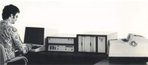
After many hours and lots of puzzles and assumptions I finally released the reverse engineered sources for the operating system of the Signetics TWIN microprocessor development system. And not just one, but two for good measure: SDOS 2.0 as well as TOS. As an indication what a massive amount of effort this took: the two OSes together take up more than 28,000 lines of assembler code!
The source code is not a simple disassembly of the binary code. Sources are annotated with ample comments to explain the inner workings. All subroutines, variables and constants have been given meaningful names, so that reading the code gives an understanding how the software works. See the example below.

This effort was necessary understanding how the software and hardware operate hand in hand. For example, although a TWIN contains two Signetics 2650 microprocessors only one of them can be active at any time. During debugging there is a constant hand-over between the primary and secondary processors, signaled by interrupts and halting of either microprocessor. Some of these interrupts are generated by the debug hardware. The user manuals and reference manuals give only a superficial description of the working of the TWIN. The source code is required to fully understand the interplay between OS and hardware.
SDOS and TOS are closely related, and reverse engineering them side-by-side reduced the overall effort as the two systems sometimes employed different software solutions to obtain the same effect. For example the File Control Block and the Job Control Block are entirely identical. It can also be seen that TOS is most likely derived from SDOS 2.0, not the other way around, as TOS corrects some of the bugs in SDOS 2.0 and refines its code.
The next step will be to do the same for the other versions of the TWIN operating systems: SDOS 4.2, EXOS, UDOS and the various versions of Tektronix’ branding TEKDOS. By comparing the sources it will be possible to work out the family tree of all OSes.
As an example of my work, have a look at just 48 of those 28,000 lines. Below is the subroutine that stores a byte in a ring buffer. The raw disassembly is given first, followed by the annotated version. If you are interested in my preferred way of working have a look at this description.
02EF				L02EF:
02EF : 3F 0D 85		"?  "		bsta,un	L0D85
02F2 : 0C 90 D4		"   "		loda,r0	*X10D4
02F5 : 16		" "		retc,lt
02F6 : 44 3F		"D?"		andi,r0	H'3F'
02F8 : CC 90 D4		"   "		stra,r0	*X10D4
02FB : 0E F0 D8		"   "		loda,r0	*X10D8,r2
02FE : C3		" "		strz	r3
02FF : 01		" "		lodz	r1
0300 : CF B0 D4		"   "		stra,r0	*X10D4,r3,+
0303 : EF 90 D4		"   "		coma,r3	*X10D4
0306 : 98 02		"  "		bcfr,eq	L030A
0308 : 07 00		"  "		lodi,r3	H'00'
030A				L030A:
030A : 03		" "		lodz	r3
030B : CE F0 D8		"   "		stra,r0	*X10D8,r2
030E : 0E F0 D6		"   "		loda,r0	*X10D6,r2
0311 : E3		" "		comz	r3
0312 : 98 08		"  "		bcfr,eq	L031C
0314 : 0C 90 D4		"   "		loda,r0	*X10D4
0317 : 64 80		"d "		iori,r0	H'80'
0319 : CC 90 D4		"   "		stra,r0	*X10D4
031C				L031C:
031C : 20		" "		eorz	r0
031D : 17		" "		retc,un
Note that it already takes an effort to determine the boundaries of a subroutine within a code listing.
Now compare this to the annotated version:
* - - - - - - - - - - - - - - - - - - - - - - - - - - - - - - - - -
*
* Subroutine PutR1DevRingbufR2 - push R1 into ringbuffer for device R2
*
* Ringbuffers start with a head, and are followed by one or more spaces in
* which data can be stored. Ringbuffers work like a stack with a fixed maximum
* size. Data is written at one end, and read from the other end. Both ends
* wrap-around, thus forming a ring.
* The first byte contains the max length, at most h'3F', often much shorter.
* Bits 0x80 and 0x40 are indicators:
*  bit 0x80 = buffer full
*  bit 0x40 = buffer empty
*
* Preserves R1,R2
* In:
*  R1	byte to store
*  R2	device number of the ringbuffer
* Out:
*  CC	LT=ringbuffer full, EQ=stored successfully
* Uses:
*  AdrB	set to the address of the ringbuffer
*  DevGetIdx	index of the current read pointer (table)
*  DevPutIdx	index of the current write pointer (table)
*
PutR1DevRingbufR2:
	; set up the ring buffer address
	bsta,un	SetAdrBToDevR2Ringbuf
	loda,r0	*AdrB		get head of ringbuffer
	retc,lt			return if full
	andi,r0	H'3F'
	stra,r0	*AdrB		clear the 'empty' bit
	loda,r0	*_DevPutIdx,r2	get current write pointer
	strz	r3
	lodz	r1
	stra,r0	*AdrB,r3,+	store byte in the ringbuffer
	coma,r3	*AdrB		pointer equals the buffer length?
	bcfr,eq	PDR1
	lodi,r3	0		wrap-around
PDR1	lodz	r3
	stra,r0	*_DevPutIdx,r2	save the write pointer
	loda,r0	*_DevGetIdx,r2
	comz	r3		write pointer has reached the read pointer?
	bcfr,eq	PDR2
	loda,r0	*AdrB		if so, mark the buffer as full
	iori,r0	ringbFull
	stra,r0	*AdrB
PDR2	eorz	r0
	retc,un